Serial Lcd Firmware

Mini controllers for robotic servos and serial display modules.
.jpg)
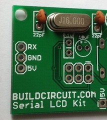
This is a simple serial lcd do-it-yourself DIY kit based on Arduino. I derived this kit from the open source eagle file available on sparkfun.com. The only difference is that I used low cost components to make it more affordable. It uses the libraries and examples published on the quickstart page of sparkfun.
This kit allows you to display all kinds of texts and numbers using only two digital pins of Arduino. You know that LCDs can be difficult to use because usually we use 6 digital pins to connect it with Arduino, so this kit includes an embedded processor Arduino based that does the hard work for you. This LCD is easy to connect to any 5V microprocessor that has a serial port, such as an Arduino, AVR, PIC, etc. However, this tutorials shows its connection with the Arduino based microcontroller only.
There are only three connections you need to make to the LCD:
RX receive : Serial receive input to the display. 5V TTL level, 9600 baud default rate, can be changed, 8 bits, 1 stop, no parity.
GND ground : Ground for the power supply. Black
5V power : Power supply, this should be 5V at up to 60mA if the back light is fully on.
The kit comes with 3-pin male and female headers for connecting the RX, 5V and GND to the Arduino board. If you fix a male header, you need a 3-pin jumper connector wire and if you fix a female header, normal wire meant for breadboard experiments can be used.
3 pin jumper wire
Tip: If you want to connect the display to a breadboard, tin the ends of the wires to make them easier to insert into the breadboard holes. To tin wire, strip about 1/4, and put some solder on the bare wire to make it stiffer.
Note that the RX input should be a 5V TTL-level signal directly from a 5V microcontroller or other 5V system. You should NOT connect the board to RS232-level voltages, which are /-10V and will damage the board see our explanation here. If you do wish to connect this display to RS232 signals, you can use a level-shifting board such as a PRT-00449 to translate the RS232 signals to TTL-level signals.
Using the display
As I already stated that I have used libraries of Sparkfun, when you power up the board, you ll briefly see a SparkFun splash screen, and then the display will go blank. To send text to the board, wait 1/2 second 500ms after power up for the splash screen to clear, then send text to the display through your serial port. The display understands all of the standard ASCII characters upper and lowercase text, numbers, and punctuation, plus a number of graphic symbols and Japanese characters. See the HD44780 datasheet for the full list of supported characters.
If you send data that goes past the end of the first line, it will skip to the start of the second line. If you go past the end of the second line, the display will jump back up to the beginning of the first line. Tip: you can simulate a scrolling window in software by copying the second line to the first line, and clearing the second line.
Note that the Arduino and other systems with bootloaders may send garbage characters to the display while the system is starting up or being reprogrammed. To avoid this, you can use a software serial library to create a separate serial port from the USB port, as in the following examples.
LCD FIRMWARE: First of all, upload this code to the ATmega328p chip of your serial LCD kit. Then, test any of the sketches given below:
NOTE that these examples were written for Arduino 1.0 and later. If you are using an older version of Arduino, you can download the older examples here: serial_lcd_quickstart_Arduino02.zip.
You can copy and paste these sketches into your Arduino 1.0 or later editing window, or download them here: serial_lcd_quickstart_Arduino10.zip.
More information
Other commands are available to change the backlight level, turn the splash screen on and off and customize it to your own text , change the baud rate, etc. See the LCD datasheet for information on all the available commands. For a more extensive example sketch that shows you how to create a scrolling marquee, create a timer, display sensor data and control the backlight, download the following examples: SerLCD Arduino example – Arduino 0023 and earlier SerLCD Arduino example – Arduino 1.0.2 and later. Alternatively, you can use the SerLCD libary found on the Arduino website. If you are using Linux, you may want to try this library instead.
Tips and troubleshooting
If the display is powered up without the RX line connected to anything, the display may fill with strange characters. This is because the display is receiving random noise on the disconnected line. If you connect the RX line to a true TX port, this will not happen. If the display is unreadable or washed out, the contrast may need to be adjusted. Send some text to the display see: the first example sketch above, then use a miniature Phillips screwdriver to gently turn the contrast 10k trimpot labeled contrast on the PCB of the kit until the text is as clear as possible please be gentle with the trimpot .
This display also has a back-light that can be adjusted for best readability, see the LCD datasheet for information. This display has a feature where if the display receives a CTRL-R character during its half-second splash screen display, it will temporarily revert to 9600 baud until power is cycled. This is to allow you to regain control of the display if you set it to an unknown baud rate. Some systems like Arduino send bootloader information out the serial port when the system starts up, which can fool the LCD into this recovery mode. If this is a problem, there are a few solutions: you can use a different pin and the NewSoftSerial library to create a TX port that doesn t get used during startup as shown in the example sketches above, or leave the display at the default 9600 baud rate, and clear the display when your program starts.
Modification by BuildCircuit- For novices and amateurs
Upload this sketch on to the ATmega328p microcontroller of the display. Use a FT232RL breakout board for uploading the sketch. Optional links: Serial_LCD_Kit. Then, upload the following code to your Arduino board. When you type texts on the serial monitor, the texts will be displayed on the LCD.
Checkout this tutorial: How to assemble serial LCD kit
Serial LCD firmware– Use FTDI breakout board to upload the firmware to your ATmega328p chip of your kit.
Upload the following sketch to your Arduino:
Resources.
- This is a simple serial lcd do-it-yourself DIY kit based on Arduino. I derived this kit from the open source eagle file available on sparkfun.com.
- Hardware: ATMEGA328 microcontroller manages all hardware TTL-Serial 0-5V interface, compatible with all Arduino variants and most other microcontrollers 20X4.
- Introduction. Grove - Serial LCD V1.0 is the new version of our serial LCDs. Attached on a single board is a 16x2 LCD and an embedded circuit based around a PIC HD44780.
0 items in cart
USD
US Dollar
Canadian Dollar
Australian Dollar
British Pound
Euro
More Currencies
Wish Lists
You are not logged in.
log in
password
Forgot your password.
No account. Register one.
SparkFun Electronics
Skip to products menu
Skip to content
Products
Support
Tutorials
Distributors
About Us
Contact
New Products
Top Sellers
Staff Picks
Gift Certificates
Classes Events
BooksBreakout Boards CablesAudioEthernetHook UpParallelSerialUSBVideo CellularAntennasEval BoardsModules ComponentsAVR MicrocontrollersButtons/SwitchesELGeneralGeneral ICsLEDs10mm3mm5mm7-SegmentOtherSMDOscillatorsPIC MicrocontrollersPICAXE MicrocontrollersSMD ICs Development Tools.NETADuCAndroidArduinoARMAVRBeagleChumbyFPGAGadgeteeriPodLPCmbedMSPPICPICAXEPropellerPSoCRaspberry PiRoombaSAMSTSTAMPWiringWIZnetDings and Dents E-TextilesAniomagicfabrickitLilyPadMaterialsEducators GPSAntennasEval BoardsModulesKits LCDsColorMonochromePort-O-Rotary ProgrammersARMAVRMAXQPICPICAXE PrototypingBatteriesBoardsConnectorsEnclosuresGeneralHardwareSocketsSolarWire RetailArduinoComponentsKitsMaterialsPrototypingSensorsToolsWireless RetiredBooksBreakout BoardsCablesCellularClassesComponentsDevelopment ToolsDing and DentE-TextilesGPSKitsLCDProgrammersPrototypingRetailRoboticsSensorsSFE WidgetsSwagToolsWireless RoboticsDriversKitsMotorsOtherWheelsSale SensorsAccelerometers1-axis3-axisBiometricsCapacitiveCurrentFlex / ForceGyros2-axis3-axisIDIMUInfraredLight / ImagingMagnetoProximityRadiationSoundTemperatureWeatherSwag ToolsHand ToolsHot-Air ReworkInstrumentsOrganizationPower SuppliesSolderingWidgets WirelessAntennasBluetoothGeneralModemNordicWiFiZigBee 802.15.4900MHzSeries 1 802.15.4 Series 2 ZigBee
images are CC BY-NC-SA 3.0
24.95
added to your cart
quantity
Only 12 left.
12 in stock
price
22.46
10 units
19.96
100 units
Add to Wish List
added to
Serial Enabled LCD Kit
LCD-10097 RoHS Compliant
Description: Calling this the Serial Enabled LCD Kit doesn t do justice to how cool it actually is. After you ve assembled this all-PTH kit, you ll be left with a fully Arduino-compatible development board that just happens to have a white on black 16x2 display built-in.
Turns out the ATMega328 is pretty far over-spec for just controlling a parallel LCD so there s a lot of horsepower left over to do whatever else needs to be done. We ve broken out all of the unused GPIO pins to 0.1 headers on one side of the board, making this more than just a great kit for beginner soldering but also an awesome development tool for experienced programmers.
In order to upload new code to the LCD Kit via bootloader you ll need an FTDI Basic Breakout and have the Board setting in Arduino on Arduino Duemilanove w/ ATmega328. The uC comes pre-programmed with the SerialLCD firmware on top of the bootloader, so if you just want to use it as a serial-enabled LCD, you won t need to do any programming.
Check the github page below for instructions on how to use the kit. The source code is also hosted over there, if you want to take a look.
Documents:
Schematic
Eagle Files
Assembly and Getting Started Guide
Datasheet
github page
Example Code
Login or
register to post comments.
Log in to post comments.
ScottMohekey
about 2 years ago
4
Is it possible to order one of these without the actual lcd.
Henrik
3
Is there a possibility in getting the board only or just without the LCD. Have couple of those waiting for to be used, no need for any more, yet : Or is this the wrong place to ask this kind of question.
Member 227114
Can you order this kit without the display so that you can use a different color or a display with 4 lines instead of 2.
Toni_K
1
You can order the serial enabled backpack LCD-00258 pre-assembled and attach it to our basic screens.
Member 236519
about a year ago
Any chance of getting just the PCB avail for sale.
ozgeekaz
2
Possibly a naive question, but are we missing resistors to limit the current in the backlight LED and the NPN transistor.
IllogicGate
The trimpot is the resistor set, I believe.
Member 297578
about 9 months ago
My backlight just burned out, so I don t know if I did something wrong or if there is no current limiting resistor.
rsp
yesterday
The backlight transistor is configured as an emitter follower. So the backlight voltage is Vbe sat below the base voltage, and since the base is at a little less than 5V it results in about 4V to 4.2V at the backlight. So if anything the backlight is underpowered and could be driven harder.
Member 217718
Do you offer this board on its own, or the kit without the LCD. It looks like a great kit, especially with the microprocessor integrated, but some prefer red LCDs.
We offer the screens and the backpack separately, but the serial enabled backpacks are pre-assembled. You could always order this kit and one of the basic 16x2 5v screens that we sell in the color that you want.
Sleepwalker3
Different circuit, the prebuilt backpack uses a PIC, so no good if you want to use as an Arduino
omsai
I m trying to use 4-40 metal hex stand-offs to separate the bottom control PCB from the LCD board.
However I can t screw in any 4-40 thread into the LCD holes. If I try the metal ground points are twisted and nearly stripped off.
What size screws are intended for the LCD board.
Ever heard of metric. I haven t checked, but they re probably M3
Member 387125
about 2 months ago
I don t know if anyone else had the same problem but it took me hours to fix so I m posting the solution here so that it may save you time in the future.
1 When you program your microcontroller and the serial enabled display SED is attached it is possible that garbage commands are sent to the SED. In this case the baud may be changed, brightness etc. Do not program your MCU while the SED is attached. In the case of the Ardunio it is possible to overcome this problem by using software serial instead of the hardware serial. see:
2 It appears that more often than not the setting that is changed is the baud rate. However this is not the only setting that can be changed. In my case I discovered that the LCD display type had been changed and caused the characters that were sent to the SED to be displayed from bottom up. IE trying to display the word Hello resulted in the o being displayed in the first line and first character position while l was displayed in the second line first character position. It is possible that the same issue could cause the text to be sent to an out of bounds position and result in nothing being displayed.
I have attempted to solve the issue by using software serial on the Arduino MCUs and ALWAYS setting up my SED in software at start up even if I have previously configured the display.
I hope that this helps some of you.
GooseSG
Can we possibly get this board by itself or at least with a 20x4 LCD. I know I can purchase the LCD-00258 but that is not the same board. It has a PIC instead of the ATmega328.
mcuaust
Is the source code for the ATMega328P available..
Does this unit work at 3.3V or 5.0V..
1 for using an Atmel chip; 1 for breaking out extra pins.
Including a picture of the white on black characters in action would be handy. This has been done for other LCD products.
AdamTolley
Did we ever figure out if this supports 3.3v.
I have 5V available to power this, but I want to know if I need a Logic Level converter for the serial connection to use this with my FEZ Panda.
Pearce
5V, it might work barely at 3.3v, but I don t think it will be enough for the backlight.
What about just 3.3v data. using 5V Vcc
Guess I better splurge and get the 2 logic level converter.
TheRobberDotCom
1 for the source.
I m keen to build one.
RobertC.
Check the github page, it has the source on it. We re moving over to using github to host most of the files since we can easily update from there.
Also, It looks identical to the white on black listed below in the related products. It s the same exact screen.
Thanks.
ditto Thanks RobertC.
Is this arduino compatible – or is it more native code. What cable / software do you need to program it.
You can use the Arduino IDE with this, and just use a simple FTDI basic for programming.
Madbodger
An ATmega328 seems like massive overkill for a serial-LCD converter, but it s nice to have all that extra storage for customization, and it s probably easier than stocking mega8s just for this and probably not a big price difference.
That s exactly it. We would just rather keep our stock to just ATMega328 s. We go through so many, if you knew how many, your head might explode.
Imma guess 1,349,297.. 3.
Valen
I like the fact that the SDA/SCL pins are broken out. same as analog pin 4 and 5 So rewriting the code could open up I2C interface posibilities aswel. However that nokia 5110 display looks like a nice bargain at just under 10 dollar. Unfortunately it needs 5 pins to be fully functional. : Tough choice.
art in louisville
Does anyone have some sample Arduino code that make use of the LCD backpack. I can t figure out how do things like set the the cursor to a location or how to set the display to 4 X 20.
Thanks
Art
Click the github page link above.
Thanks for the reply. I ve been there looking for sample code and all I could find was the code for the backpack itself. I dl d and install the new code into the backpack but I don t understand how to sent the special commands to do things like clear the display or set the display for 4X20 I m using NewSoftwareSerial to connect to the backpack and I can print Hello World but when I try to send a special commands it either prints garbage or nothing. Art
Good morning all. I m still looking for help sending commands to the serial backpack. I found the commands on the github page but not how to send then to the device. Art
If you go into the Arduino IDE and set the board to Duemilinove or Nano w/ ATMega 328 then bring in the Serial Monitor and type in the commands using the correct baud rate of course, that should work. Oh, and you probably know this, but make sure to plug in the board to the computer BEFORE opening the IDE. :
randumnumber
Probably a very noob question but can this easily be interfaced with a serial port on a computer. and is it HD44780 compatible.
It could be interfaced in some way using the FTDI Basic. Not sure about the HD44780 compatibility though as I don t know what that is. :D But the onboard code is basically Receive stuff from Serial Monitor – Print stuff from Serial Monitor – Wait for more stuff from Serial Monitor, so all you need to do is send it serial commands and it ll do its thing.
rmoody
Had to really dig hard to find out how to use this and the sketch I did find had many errors where special commands were sent which required it to me mostly re-written. Learned a lot however. The documentation is really lacking. For instance, no mention of how to send and display special characters. I would also like to see this kit without the LCD for those of us that would like to use a different color or have and LCD already or have messed up the PCB. Lastly, there is no assembly instructions and the photos don t show many details that you need to see.
Teque5
https://github.com/jimbloom/Serial-LCD-Kit/wiki/Serial-Enabled-LCD-Kit-Datasheet
Teit
I ve managed to alter the setup of the Serial Enabled LCD Kit and now I cannot read anything of the diaplay or anything else.
How do I reset it for use at 6900 baud and everything else. What should I send as command 0x7C –. .
Can anyone help me with a set of code for reseting the backpack, e.g. comm 9600 baud etc. Please.
Have you tried 0x81 followed by 0x04 – the github page seems to indicate that that will reset the baud rate to 9600 – however you will need to know which baud rate it is currently running at.
Have you asked this in the forums. That would be more conducive to a troubleshooting dialog.
I ll try 0x81, 0x04 next time. Hope it works, I ll write code to try the different baud rates.
And next time I ll use the forum instead of here. Cheers, Teit
I would be really cool for the next revision to include the capability to run off of 3.3v logic.
I have creatively soldered a logic level converter to the backpack using some of the broken out pins leaving the standard three wire port alone and now I can hook it up to my Fez Panda with 4 wires: 3.3v, 5v, Data 3.3v and Ground.
A better solution might be to eliminate the 3.3v reference feed with a voltage divider, or just get logic that can handle 3.3v from the get-go.
So ideally I would be able to feed it through the standard jst 3 pin connector 5V, Ground, and Data at 3.3 V.
That would be nice.
tmy3141
My display unit LCD-10097, has accidentally become corrupted. In particular the back light has turned off and since I have not yet been able to communicate with the unit I am unable to debug my code. Is there a way to reset the unit to defaults as shipped.
Hum, you might want to talk to tech support. I don t think there s a reset, but you can surely reprogram it. See what they have to say, techsupport sparkfun.com
sridenour
This this is pretty awesome, but would be even more awesome awesomer. if you could upload custom characters over serial. The LCD itself seems to support this, but the Serial LCD firmware does not.
It shouldn t be too hard to add after all, the LiquidCrystal library it uses has a function just for this. I guess it s finally time for me to get an FTDI Basic.
I wonder if you can do this by just sending the instructions to do it as if they were characters to print. Provided none of the data is something the ATmega328 will intercept as an instruction to change the baud rate or something.
edit: Evidently not, the ATmega328 just puts whatever you send outside of the commands listed on github into the LCD s display RAM.
Not to reply to myself again, but I updated the firmware and it now can upload custom characters to the LCD s CGRAM. I made a post about it with some example code and the code for the updated firmware on the forums
I wonder if SparkFun could add this to their git repo.
Smaks
These things are just the bomb. Great price for what you get.
I confess I haven t been using them as intended – once I have a project all figured out with the arduino and the breadboard etc I order one of these and write my sketch to it. Any time I am using an arduino and the liquidcrystal library and I am ready to go from prototype to finished project, this is my go-to kit. Just wish it included a socket for the IC.
I ve got it driving my diy networked home thermostat:
Cheers.
Member 116775
Are there any instructions or tips for putting this together, or can I just infer where stuff goes by looking at the images above and the labels on the circuit board. I m not particularly great at reading schematics.
Thanks,
Adam
Allan
its awesome. not for convert a lcd to serial, but because you have a arduino in a LCD. maybe sparkfu can sell this as LCDuino Arduino on a lcd
sparkieee
can i buy this then get a 20x4 lcd for it. or is their a kit like this with a 20x4 already.
N00b_Programmer
I have ported LiquidCrystal library for use with the serial LCD you can look at my code here. Still working on finishing all the documentation. But putting up for now hopefully someone will find it usefull.
-Thanks
mikemack
last year
i like this kit allot but it has its challenges, i am trying to figure out how to get the back light back on, it seems to have gotten a command to turn it off. and not much seems to want to turn it back on. the other thing i would like to know is that, can i reflash it with a different firmware using a ftdi without taking the lcd off.
chrocwe
Hi. I m having trouble with this device. I am sending serial.print text to the LCD, but it seems pretty erratic. I wonder if it was damaged when I soldered it to the board. There is not chip holder in the kit. Sometimes it does not power up: I ll have to check it out for bad connections. Should the device should respond to serial.print similar to the way serial monitor works.
Wailer
The Serial LCD Kit – retail same kit, different packaging, has a quite good tutorial by Jimbo.
Strange there s no link to there from this page, Serial LCD Kit Landing Page
Xykon
I love this thing. You can use it for rapid prototyping and then switch to a native interface for the LCD later on and you still have a use for the serial module as all the pins or at least most of them are broken out on the headers. Having a header for the FTDI breakout board is great as well for quick testing you should like to it at the bottom.
Overall a really great product.
YouBlob
about 11 months ago
Hi, can someone explain this to me
Quote: In order to upload new code to the LCD Kit via bootloader you ll need an FTDI Basic Breakout
Is that to change the fonts on the LCD display or GUI.
Or is it needed to what type of data to display on the LCD.
has anyone got this to work with lcd smartie, or another program like it..
dbranger94
The only complaint I have is that both interrupts are taken by the LCD D2 and D3 on the ATMega. Not a problem unless you are using the kit as a stand alone unit to read and display RPM.
ae9k
about 3 months ago
Can someone clarify the use of both interrupts. Since there s an ATmega328 uC piggy-backed on this display it s not clear to me if the interrupts used belong to the onboard ATmega328 or to the Arduino to which this display is wired.
If it s the host Arduino s two interrupts, is this a limitation of the SoftwareSerial library used to communicate with the display or something else.
I was trying to write to the display from within an interrupt service routine and doing so locks up the host Arduino so I m guessing it s the host Arduino s two interrupts. If this is the case, it s too bad the compiler preprocessor doesn t catch the overallocation of interrupts.
Martin_B
Same problem here. It would be nice, if this could be implemented in a future design. Apart from that, It is a great board, which I use in several projects.
emihackr97
Hi, any chance of getting a firmware update for I2C and SPI interface aswel. it would be great.
Sciguy
about 8 months ago
Just a tip – if you want to reprogram this, but you don t have an FTDI breakout or the like, you can use another Arduino board. Just remove the Atmega chip, and connect the 5v, Gnd, Reset, Tx, and Rx lines appropriately.
Member 74037
about 7 months ago
Has anyone directly powered this kit using a 5V wall adapter https://www.sparkfun.com/products/8269. Is it as simple as connecting the ground and VCC leads from the JST connector, perhaps using a barrel jack adapter https://www.sparkfun.com/products/10288.
about 6 months ago
Anyone have experience using this kit in a wall powered setup.
Member 207406
Easy kit to solder together, I ve got very little soldering experience, I was blown away by how much easier this was to solder with the correct solder than the beastly large stuff I ve been trying to use on everything else. It still took me about 45 minutes to get all together, but I was being pretty meticulous and checking pretty much every joint.
My desoldering skills need work though, I forgot to mount the 10k resistor until after I soldered the headers to hold the LCD to the control board. It seems in trying to get them apart I ve destroyed both boards : Glad I picked up an IC socket so I can at least salvage the ATmega 328 by just pulling it out. Practice my obviously lacking desolder skills on the rest of the components and eventually order another of these to play with.
adruniocaveman
about a month ago
Howdy TechoJunkies.. I am currently building one of these from scratch and it is eventful.. The problem i am having is sending commands to the backpack. I.E. clear, scroll, etc. it just echos them on the display.. I am using the serial terminal in the arduino ide.. Ideas.. I am using the
code that is on the github page with no alterations.. built the display backpack per schematic.
Curious..
last month
You need to send the commands as bytes, and sending them from the IDE serial window sends them as ASCII characters. Try sending the commands via the Arduino board itself if you can, or try using a different terminal program such as CoolTerm, which allows you to choose the formats of commands that are sent.
Thanks for the wisdom.. I actually built this from identical components on waferboard with wirewrap 33 ga white wire, Look like art.. PITA but fun. ant that what hackin s about.. Will post a picture when finalized if un s want to scope it out.. Worked of a picture of your bare pcb and schematic.. Fun trying to look at it in reverse in Eagle..
about 3 weeks ago
Success i have completed my homemade wirewrapped version of this. Functions perfectly.
Toasty
0
Has anyone added a button or a joystick onto kit, to then scroll through what text was sent to it from their arduino.
I haven t heard of anyone doing that particular hack on this product, but it probably wouldn t be that hard to implement.
Related Products
FTDI Basic Breakout - 5V
Out of stock
DEV-09716
14.95002
Description: This is the newest revision of our FTDI Basic. We now use a SMD 6-pin head
Read Full Description
Out of stock
Add to Wish List
Added to your cart.
Proceed to checkout
Logic Level Converter
In stock
BOB-08745
1.95002
Description: If you ve ever tried to connect a 3.3V device to a 5V system, you know
In stock
XBee Explorer USB
WRL-08687
24.95002
Description: This is a simple to use, USB to serial base unit for the XBee line. This u
Female Headers
PRT-00115
1.50002
Description: Single row of 40-holes, female header. Can be cut to size with a pair of w
EasyDriver Stepper Motor Driver
ROB-10267
Description: The EasyDriver is a simple to use stepper motor driver, compatible wi
Selected by our staff
Serial Enabled LCD Backpack
31 available
LCD-00258
16.95002
Description: The serial enabled LCD backpack allows you to control a parallel base
31 available
Basic 16x2 Character LCD - White on Black 5V
LCD-00709
15.95002
Description: This is a basic 16 character by 2 line display with a snazzy black backgro
LCD Add-On for SIK
Only 11 left.
DEV-10054
Description: Nothing is cooler than visual feedback for a project. Well, there are cool
Only 11 left.
16x2 Parallel LCD Add-On
29 available
RTL-09761
Description: This is the same product as the LCD Add-on for SIK. The difference is this
29 available
Serial LCD Kit - Retail
17 available
RTL-10768
25.95002
Description: This is the same product as the Serial Enabled LCD Kit. The difference is
17 available
Enclosure - Flanged Red
PRT-11366
7.95002
Description: These beefy, bright red plastic enclosures will give your widget the prote
SparkFun USB Mini-B Cable - 6 Foot
CAB-11301
3.95002
Description: This is a USB 2.0 type A to Mini-B 5-pin cable. You know, the mini-B conne
Sharing Ingenuity
GitHub
YouTube
Vimeo
Google Plus
Flickr
RSS
SparkFun.
SparkFun is an online retail store that sells the bits and pieces to
make your electronics projects possible. Whether it s a robot that can
cook your breakfast or a GPS cat tracking device, our products and
resources are designed to make the world of electronics more accessible
to the average person. In addition to products, SparkFun also offers
classes and a number of online tutorials designed to help educate
individuals in the wonderful world of embedded electronics.
Resources
Feeds
Forum
SparkFun Education
SparkFun IRC Channel
BatchPCB
Jobs SparkFun
Sell Your Widget on SparkFun
Become a SparkFun Distributor
Request SparkFun Sponsorship
Take the SparkFun Quiz
Tell us about a project
SparkFun Kickstarter Projects
Feedback
What s on your mind.
For which department.
Please include your email address if you d like us to respond to a specific question.
SparkFun Electronics
Boulder, Colorado
Customer Service.


How to Update a Samsung TV LCD Firmware. Firmware is a software upgrade used to fix or patch programs and data structures that internally control various electronic.
